

Hi all, hope you had a great Labor Day weekend. September always brings that back-to-school feeling. Fresh notebooks, sharp pencils (am I dating myself), and a clean slate. So, today I’m starting a four-part series on the business of actuators. At Core Matter, we focus on the business and deployment realities of physical AI. I’m taking the same approach here: understanding enough of the engineering to figure out what it means for cost, manufacturing and the supply chain.
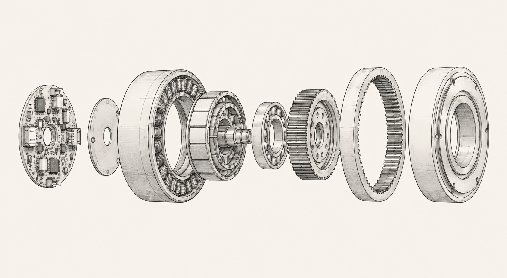
Actuators can account for up to 70% of a humanoid robot’s bill of materials. A typical humanoid packs dozens of them. A design decision at one joint cascades down the robot.
The key question running through this piece is: where does a robot pay for torque?
More gearing shifts the engineering burden toward precision mechanics. Less gearing shifts it toward the motor, electronics and thermal system. Repeated across dozens of joints, that single design decision ends up deciding what the robot costs to build and which suppliers capture the value.
Actuators are complex machines. Over the past few weeks I have spent a lot of time learning how they actually work. I’m thankful to the authors of the many resources I have relied on along the way. They are cited in the Appendix.
By the end of this piece, you’ll know what is inside a humanoid joint, why it is built the way it is, and how that design choice redistributes value across the supply chain, from a small set of precision gear-cutters to a global market for rare-earth magnets.
This is Part 1. Subscribe to get the future posts in your inbox as they go live.
Sections
What’s Inside a Humanoid Joint?
Why Gearing Is the Key Architectural Decision
Five Actuator Metrics That Matter
What Gearbox Choice Tells You About the Supply Chain
Why QDD Changes Actuator Economics
Where Different Actuator Architectures Get Used
Where the Robot Pays for Performance
Acknowledgements
Appendix A: What’s Inside an Actuator
Appendix B: How to Read an Actuator Spec Sheet
Appendix C: How the Three Gearbox Architectures Work
1. What’s Inside a Humanoid Joint?
Before we look inside the actuator, I want to clarify three terms that repeatedly come up: joint module, motor driver and actuator. The industry uses them interchangeably, but they are actually different things.
A joint module is the mechanical assembly: motor, reducer, encoder, bearings, housing, and on some designs a brake. Two filings classify the components differently: one groups the encoder inside the joint module, the other treats it as a separate control component alongside the driver board.
A motor driver is the power and control board. It turns battery DC into three-phase current for the motor and closes the control loop.
An actuator is the broad category word that can cover both. Two vendors quoting an actuator can therefore be quoting two different bills of materials, one with the driver board inside the housing and one selling that board as a separate line.
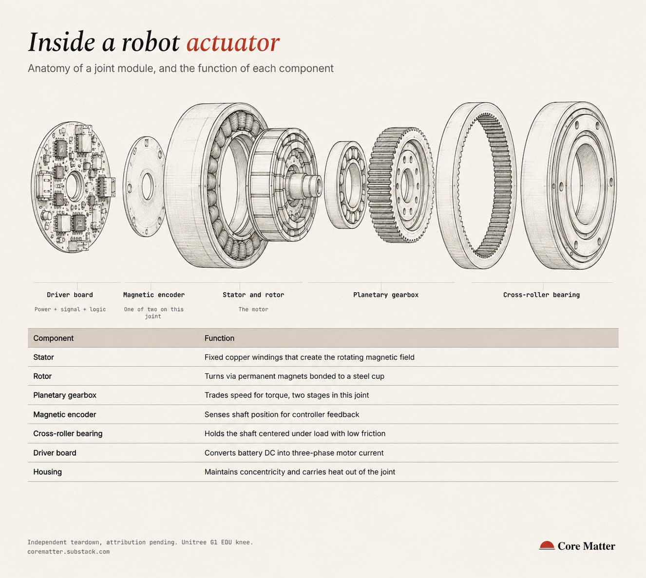
For full details of each component, see Appendix A of this post.
2. Why Gearing Is the Key Architectural Decision
Electric motors and humanoid joints naturally operate in very different regimes. Motors are most compact and efficient when spinning fast. Humanoid joints need to move relatively slowly while producing turning force, or torque.
A reducer, or the gearbox, bridges the two: it reduces the motor’s speed for greater torque at the joint.
A higher reduction ratio gives the joint more mechanical leverage, but that comes with costs. Here are three of the penalties, and how each translates into economic trade-offs elsewhere in the robot:
Energy loss means bigger batteries and shorter runtime. Gears lose some energy to friction. A single planetary stage returns 95%-98% of the motor’s work, a strain-wave stage drops to 85 to 90%. A stacked two-stage planetary train (we explain more what that is in Appendix C) degrades further: squaring that range gives roughly 90% to 96%, an arithmetic estimate rather than a measured figure. Across dozens of joints, those losses mean more heat, shorter runtime, and potentially larger batteries or additional cooling.
Heavier joints increase BOM costs. Reducers contain precision steel components. And steel is very heavy. A heavier knee doesn’t merely cost 300g more. The hip actuator then needs more torque to move that knee, which means bigger motor, more copper/magnets, stronger bearings, more current and potentially a larger battery. Mass at each joint compounds through the robot.
High reduction lowers force transparency and dynamic response. High gearing mechanically isolates the joint from the motor. That makes the joint harder to move from the outside. It also makes the motor less able to feel external forces. One reason is reflected inertia: the motor’s rotational inertia is amplified through the gearbox by the square of the gear ratio.
This leads to one of the central design decisions inside a humanoid is, where do you pay for torque?
And it has implications of where the cost sits in the actuator.
At a simplified level, gearbox designs can sit on either end of the spectrum:
a) Smaller, faster motor + high-ratio reducer
b) Larger, high-torque motor + lower-ratio reducer
At the high-reduction end (a), more of the engineering burden sits in the reducer: precision gears, tight tolerances, specialized manufacturing and, depending on the architecture, multiple reduction stages.
At the low-reduction end (b), more of it shifts into the motor and electrical system: magnets, copper, higher current, electronics handling motor current and thermal management.
So, this design choice determines which components matter most, which suppliers are difficult to replace, and where value accrues inside the actuator supply chain.
3. Five Actuator Metrics That Matter
These are the five metrics to look at when evaluating an actuator claim, and what each tells us about the robot behind it.
Continuous vs peak torque: Can the robot sustain the demo workload?
Peak torque tells you what a robot can do briefly. Continuous torque tells you what it can do repeatedly in deployment.
Torque density: How much actuator mass is required to produce useful force?
Higher torque density means more torque for the same actuator mass. That cascades into lighter limbs, smaller upstream actuators and potentially lower overall BOM.
Backdrivability: How naturally can the robot absorb and sense external forces?
This matters for walking, manipulation and human interaction.
Backlash: How much mechanical uncertainty exists when direction reverses?
This matters for precision manipulation.
Shock tolerance: Can the hardware survive repeated real-world impacts?
This matters for reliability, maintenance and useful life.
The full list of actuator metrics is at Appendix B.
4. What Gearbox Choice Tells You About the Supply Chain
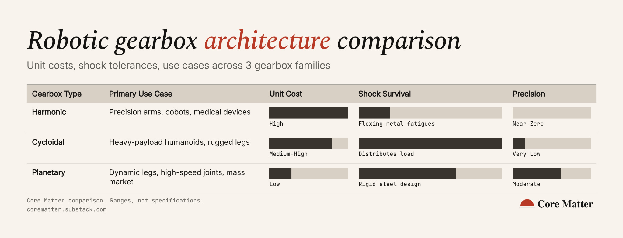
The three major gearbox architectures solve the same basic problem, but their manufacturing requirements create very different supplier economics.
Harmonic drives provide compact high reduction and near-zero backlash, but require specialized precision manufacturing. This includes grinding a flexpline that has to flex millions of cycles without cracking.
That manufacturing base has historically concentrated in Japan, and a few players such as Harmonic Drive Systems and Nabtesco. Chinese entrants, including Laifual and Leaderdrive, are now taking share, and the shift looks more like a maturing competitive base than a pure price war: Laifual’s most recent interim results showed shipments and margin both rising, not falling. We’ll cover more on Part 3 of the series.
Planetary drives prioritize efficiency, shock tolerance and manufacturing accessibility. The gears supply is not scarce; it can draw from a much broader conventional gear-manufacturing ecosystem. The challenge is to hold tight tolerances at high volumes. Low-ratio planetary is also the architecture behind QDD, which trades gearbox difficulty for another supply chain problem, covered in the next section.
Cycloidal drives serve high-load applications. The hard part to source is the eccentric disc’s precision profile, machined by a narrower set of shops than planetary gear-cutting, though a broader one than harmonic. They are less common in humanoids today, though at least one Chinese humanoid maker names a cycloidal joint as a core technology, so “heavier, so avoided” does not hold across every design.
The design, pros and cons of each gearbox architecture are covered in detail in the Appendix C.
5. Why QDD Changes Actuator Economics
If you follow humanoids coverage, you probably have come across the word QDD quite a bit. QDD, or Quasi-direct drive in full, is an actuator design philosophy, not a gearbox type. It refers to a system where a high torque motor is paired with a very low reduction gearbox (3:1 - 10:1). Quasi means almost: the motor is almost directly driving the joint, with just enough gearing to increase torque while preserving much of its responsiveness to external force.
QDD gearboxes are predominantly planetary due to their low cost and high mechanical efficiency (95%+), though low-ratio cycloidal variants are emerging.
The MIT Mini Cheetah actuator, developed by Ben Katz, became an influential reference design for modern QDD modules. Mini Cheetah used a single 6:1 planetary stage delivering 6.9 N·m continuous torque and 17 N·m peak. By contrast, traditional industrial robot wrists run gear ratios between 50:1 and 100:1 to statically lock loads. Even humanoid knees, which require higher torque to hold deep crouches, use low-ratio multi-stage planetary setups (eg, 22.5:1), staying well below industrial standards to preserve shock tolerance.
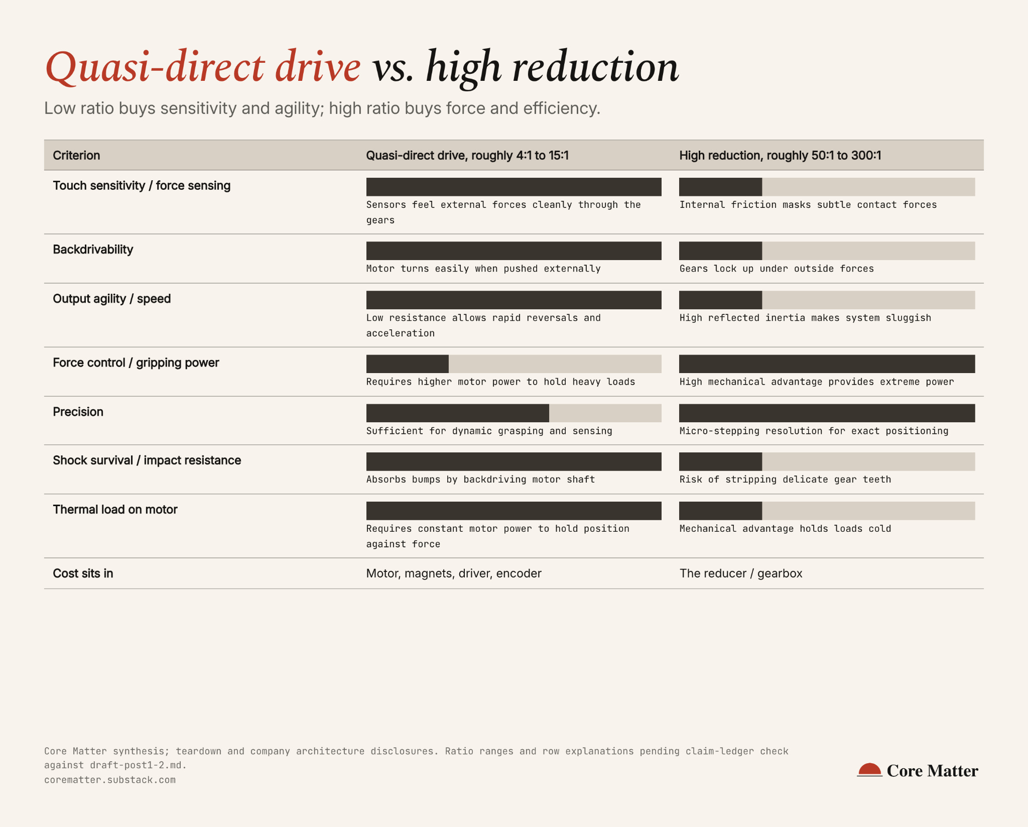
QDD changes where the robot pays for torque
Traditional robot architectures often pair smaller, fast-spinning motors with high-ratio reducers to generate torque at the joint. More of the engineering burden therefore sits in the reducer.
QDD flips this. More of the torque comes from the motor, which means, more magnets, copper, and more demanding electronics and thermal management, in exchange for a simpler, lower-ratio reducer.
By shifting the workload to a powerful, high-diameter motor, QDD delivers three mechanical advantages:
High backdrivability. At a low ratio you push the output and the motor turns. The robot feels external force through the joint itself, enabling soft compliance. In contrast, a high-ratio gearbox behaves closer to a one-way valve.
Low reflected inertia. Low reflected inertia allows a humanoid to react more quickly to disturbances, such as a stumble.
Shock tolerance. A walking robot hits the ground several times a second. Lower-ratio designs generally tolerate impact better.
That mechanical shift has economic implications.
High ratio keeps the burden in the gearbox: precision-ground teeth, tight tolerances, and a small set of manufacturers who can hold them. High ratio buys precision at the cost of a narrow gear-cutting supplier base.
Low ratio pushes the burden into the motor and its electronics instead: a wider stator, more magnet volume to generate torque directly, more copper in the stator windings, and a driver board built to handle it. Low ratio buys shock tolerance at the cost of rare-earth magnet and higher-current electronics.
Even though electronics is more complex, QDD can lower the total actuator BOM of a robot. Below are some reasons:
Supply Chain Accessibility. Low-ratio planetary gearboxes are standard industrial components. They can be made by widely available gear-hobbing equipment. Harmonic reducers need a much more specialized supplier base. That being said, a lower-ratio design needs more concentrated magnets to make up for the less sophisticated gearing. China accounts for 94% of global sintered neodymium-iron-boron magnet production, up from about 50% two decades ago. [12]. We’ll cover in Part 3 of this series
Cost & Efficiency Gains. According to SemiAnalysis’s June 2026 G1 teardown, low-ratio planetary gearboxes achieve 95% to 98% efficiency (vs. 85% to 90% for strain-wave) and up to 80% cheaper.
Driver Localization. Public financial filings from Leju, a humanoid maker in China, show driver expenditure per joint module fell 83% in two years.
6. Where Different Actuator Architectures Get Used
Humanoids do not use a single “one-size-fits-all” actuator. Different joints optimize for different combinations of force, precision, impact tolerance, mass and packaging.
Legs and hips prioritize shock absorption, rapid acceleration, and heavy force production. To protect from ground impact, these joints lean heavily toward QDD planetary setups or high-force linear actuators.
Wrists and arms prioritize spatial precision, high torque-to-weight ratios, and compact form factors. They often employ harmonic reducers to maximize holding torque in tight spaces. Alternatively, QDD motors are placed centrally, then power is routed through tendons to keep the limbs light.
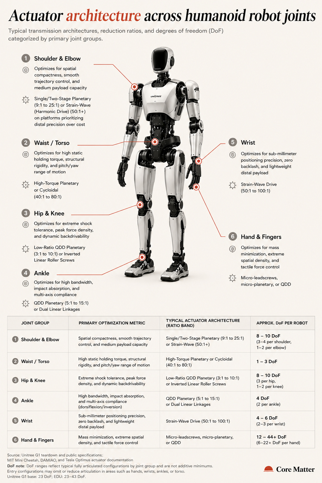
Current humanoid designs show how these trade-offs play out in practice:
Tesla Optimus Gen 2/3 uses harmonic reducers across rotary body joints (shoulder, torso, wrist roll) for compact form factor and precision, while it uses linear actuators for high-force joints like knees and elbows.
1X’s NEO hand uses a tendon-driven Quasi-Direct Drive (QDD) architecture at approximately 5:1 to 15:1 gear ratios. Motors are housed in the forearms/torso to keep distal limb inertia minimal and limbs safe around humans.
Unitree highlights its core architecture in investor briefings as a “high-bandwidth force-controlled quasi-direct-drive planetary rotary joint”. It combines a high-torque motor, low-ratio planetary gearhead, and rapid torque-control loop. (See Unitree’s 3-hour Investor Q&A for details).

7. Where the Robot Pays for Performance
This piece we covered the key question to ask when looking at actuators for humanoids or any robots: where the robot pays for performance. High reduction puts more of the burden into precision mechanical components. Low reduction shifts it toward motors, magnets, electronics and thermal management.
That architectural choice flows through the entire robot: how it moves, what it costs to build, which components become critical, and ultimately which suppliers capture value.
On Friday, we’ll put dollars against those choices: what a humanoid actuator actually costs, using audited filings and factory quotes, and why published estimates put actuators anywhere from 21% to 70% of a humanoid’s BOM. [1][4]
Acknowledgements
Thank you to Parth Ingle (@parthingle_x), Grant (@grantg07), and Sajiv Shah (@sajiv_shah) for technical review and feedback on earlier versions of this piece. Any errors or interpretations that remain are my own.
Appendix A: What’s Inside an Actuator
Below are the key parts inside an actuator and what they do.
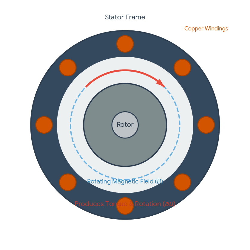
Stator. The stator is the fixed half of the motor: a stationary ring of copper coils. When electricity passes through these coils, it creates an electromagnetic field.
Rotor. The rotor is the turning half. Permanent magnets (sintered neodymium-iron-boron) are bonded to a steel structure. As these magnets interact with the stator’s magnetic field, they force the rotor to spin.
The motor is built primarily from laminated electrical steel, copper wire, magnets and epoxy.
Reducer. Also called the gearbox, it reduces rotational speed and turns that into greater turning force, or torque, at the output. It is typically built from hardened steel components. There are three main types of reducers used in robotics, which we’ll cover later in the Appendix. The choice of gear family can be a major driver of joint cost.
Encoder. The encoder tells the robot’s computer what angle the joint is at, how fast it is moving, and which direction it is turning. It can use a magnetic ring or optical disc read by a sensor. Some joints use dual encoders, one on the motor and one on the output.
Bearings. Bearings support the actuator’s rotating components and carry loads between the actuator and the robot’s limb. They typically consist of rolling elements, such as balls or crossed rollers, running between two hardened races.
Driver board. The driver board turns commands from the robot’s main computer (e.g., an edge compute device in the chest or head) into controlled electrical power for the motor. It typically contains power transistors, a microcontroller and connectors.
Housing and brake. The housing holds the actuator assembly together and helps manage structural loads. It also has to deal with heat generated by the motor. Some joints include a brake to hold position when required.
Appendix B: How to Read a Humanoid Actuator Spec Sheet
Let’s cover the key terms to understand when reading an actuator’s spec sheet. One way that’s easier for me to understand these mechanical terms is to link them back to the human form and think about our own joints, muscles and movements.
Gear Ratio (or Reduction Ratio) (N:1) is the mechanical trade-off between speed and torque inside the actuator. It is usually written as N:1 (e.g., 9:1, 40:1). A high-speed, low-torque electric motor turns a gearbox. The gearbox slows down the rotation at the output shaft by a factor of N, while multiplying the motor’s torque at the output by approximately N, before accounting for efficiency losses.
Gear ratios are all about mechanical leverage.
High ratios (40:1 to 100:1) function like a low gear on a bicycle. They provide greater mechanical leverage for producing and holding torque, but reduce output speed.
Low ratios (3:1 to 9:1) function more like a springy, dynamic athlete’s limb. They are responsive and fast but provide less mechanical leverage, so the motor needs to do more of the heavy lifting.
Peak torque vs. rated / nominal torque (N·m). Rated / nominal torque is the torque a motor can produce continuously without exceeding its thermal limits. Peak torque is the higher torque a motor can produce for a short period before heat becomes the limiting factor. A large gap between peak and nominal torque means the actuator cannot sustain its headline peak performance continuously.
Torque is raw rotational strength. A bodybuilder’s bicep generates torque to curl a 100-lb dumbbell. It answers: “How much turning force comes out of this joint?”
Torque density (N·m/kg) is turning force per kilogram. It is an important metric in robotics because mass at the end of a limb costs torque at every upstream joint. Vendors rarely list this number directly; you calculate it by dividing torque by total actuator mass. Today’s merchant joint modules typically yield 45 to 75 N·m/kg at peak. Always check continuous torque density too, as thermal limits keep sustained performance below peak figures.
Think of an elite rock climber vs. a big powerlifter. A rock climber might be able to lift less absolute weight than the powerlifter, but can generate high force relative to body weight. In the same way, torque density tells us how much rotational force an actuator produces relative to its mass.
High torque density is important for robots because a heavier actuator requires more torque just to move the limb itself. It is also a major engineering challenge: producing more torque generally requires more motor material, which adds mass.
Backlash (arcmin) is mechanical slop, often measured in arcminutes. One arcminute is one-sixtieth of a degree. Turn a gear train one way, then reverse it, and the output can briefly remain stationary while the teeth cross the gap between them and begin transmitting force in the opposite direction.
Think of backlash like looseness in a joint. Too much can cause instability and reduce accuracy in fine tasks like threading a needle.
Very low backlash is useful for precision tasks, although some gear designs require small clearances for lubrication, thermal expansion and reliable operation.
Backdrivability describes how easily an external force applied at the output can drive the motor backward through the transmission. It can be characterized by the amount of output torque required to move the joint. A highly backdrivable joint can respond more naturally to external forces.
The analogy: a backdrivable joint is like a relaxed arm. When someone pushes your wrist, your arm yields smoothly. A poorly backdrivable joint behaves more like a rigid arm that resists being moved from the outside.
Backdrivable designs are useful for human interaction, force control and dynamic movement. Less-backdrivable designs can be useful when stiffness and holding loads are more important.
Shock tolerance describes how well an actuator survives sudden impact loads, such as when a robot’s foot hits the ground during walking. Vendors may characterize it using peak or momentary torque relative to the rated figure. The merchant modules reviewed above range from about 2x to 4.6x rated torque.
Appendix C: Comparing Gearbox Architectures: Harmonic, Cycloidal, and Planetary Drives
Below are the three main gearbox architectures used in robotic joints.
Harmonic, cycloidal and planetary gears all transfer rotational power and reduce speed. The difference is in how they do it. The three architectures make different trade-offs between positioning accuracy, shock tolerance, weight, efficiency and manufacturing complexity. Below, I’ll use the same human-anatomy analogies to help visualize each architecture.
Harmonic Drives (Flexing Cartilage & Tendons)
How it works: A harmonic drive uses a flexible, thin-walled steel cup that deforms inside a rigid outer ring to transmit motion.
Anatomy analogy: Think of flexible cartilage or tightly tensioned tendons. The architecture relies on controlled elastic deformation rather than only rigid gears rotating against one another.
One-liner: Premium precision at a cost.
Strengths: Very low backlash and high reduction ratios (often 50:1+) in a compact, lightweight package. This makes harmonic drives useful for applications such as precision industrial and surgical robots.
Drawbacks: Higher unit cost, specialized manufacturing requirements and lower tolerance for shock loads than some alternative gearbox architectures. The flexible component is also subject to fatigue over its operating life.
Cycloidal Drives (Interlocking Vertebrae)
How it works: A lobed disc moves eccentrically inside a ring of stationary pins or rollers, distributing forces across multiple contact points.
Anatomy analogy: Think of interlocking spinal vertebrae. Loads are distributed across multiple contact points rather than concentrated on a small number of gear teeth.
One-liner: The rugged option for heavy loads.
Strengths: High shock tolerance, high load capacity and low backlash. Multiple contact points allow the gearbox to distribute sudden loads across the mechanism.
Drawbacks: Cycloidal drives tend to be heavier and bulkier and can be more complex to assemble. This makes them more suitable for high-load applications where ruggedness matters more than minimizing joint mass.
Planetary Gearboxes (Skeletal Ball-and-Socket Joints)
How it works: A central “sun” gear drives multiple “planet” gears inside an outer ring gear.
Anatomy analogy: Think of a shoulder or hip joint: a rigid structure that distributes force across multiple contact points.
One-liner: The scalable, cost-effective workhorse.
Strengths: High energy efficiency (often 95%+ for a single stage), good shock resistance, and an established manufacturing base using conventional gear-making equipment. Low-ratio planetary gearboxes are commonly used in Quasi-Direct Drive (QDD) actuators at ratios such as 3:1 to 10:1.
Drawbacks: Planetary gearboxes have mechanical backlash. Stacking multiple stages to achieve higher gear ratios can increase backlash, friction, weight and complexity.
Appendix D: Sources Cited
[1] LeJu / Lejoin Intelligence ChiNext prospectus, audited by Tianjian, procurement tables pp. 1-1-187 to 1-1-188.
[4] SemiAnalysis, “China’s Unitree Will Dominate Global Robotics,” 2026-06-09, read via Core Matter’s own capture of the piece.
[12] International Energy Agency, “China’s share in rare earth magnet production, 2024,” Rare Earth Elements report, April 2026: https://www.iea.org/data-and-statistics/charts/china-s-share-in-rare-earth-magnet-production-2024